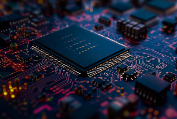
Designing electronics for aerospace and automotive applications isn’t just about performance; it’s about survival. PCBs in these environments face harsh, unpredictable conditions: temperature swings, constant vibration, and moisture exposure. When failure can affect safety, performance, and compliance, high-reliability engineering becomes non-negotiable.
If you’re working on a PCB design for mission-critical use, or you’re evaluating a PCB design service partner for a custom PCB, understanding environmental failure modes and prevention techniques is key. Let’s break it down in a practical, real-world way.
Why Harsh Environments Are So Challenging
Aerospace and automotive electronics aren’t sitting in controlled labs; they’re mounted on aircraft fuselages, inside engine bays, within vehicle cabins, or on flight computers. That means three major reliability threats are always present:
1. Humidity
Moisture can trigger corrosion, dendritic growth, or conductive leakage across traces and vias. The damage often builds slowly, showing up months, not hours, after deployment.
2. Vibration
Engines, flight surfaces, suspension systems, and propulsion systems generate continuous vibration. Over time, this causes solder fatigue, connector failure, and cracking in plated through-holes.
3. Thermal Cycling
Going from freezing altitude temperatures to high engine heat stresses materials. PCB laminates, copper, solder, and components expand at different rates, leading to mechanical stress, microcracks, and eventual failure.
In reality, these stressors don’t act alone; they compound, accelerating aging and weakening structural integrity.
Smart PCB Design Choices That Improve Reliability
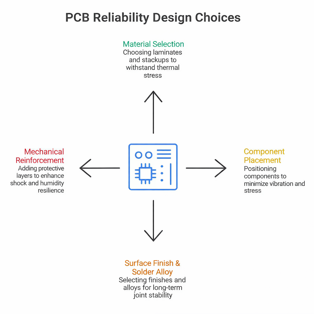
Having a solid layout and structure helps ensure the design performs under extreme conditions. These engineering choices matter:
1. Material Selection
High-Tg, low-Cte laminates and controlled stackups reduce warping and cracking under thermal load.
2. Component Placement
Place heavier or taller components near mechanical support points. Avoid long unsupported leads during vibration-exposed mounting.
3. Surface Finish & Solder Alloy
Finishes like ENIG or immersion silver paired with automotive-grade solder alloys increase long-term joint stability.
4. Mechanical Reinforcement
Underfill for BGAs, conformal coatings for moisture, and potting compounds, where needed, improve shock and humidity resilience. If you’re building a custom PCB for rugged environments, every detail, even copper thickness, can impact durability.
Additional Reliability Techniques Engineers Often Overlook
Even experienced teams occasionally miss subtle but important durability layers. For example, incorporating controlled impedance routing and signal shielding can prevent EMI instability under high vibration. Another overlooked factor is edge plating, or Via-In-Pad Plated Over (VIPPO) technology. Both reinforce the structure while improving electrical performance, especially useful in environments where connectors or modules experience repeated mechanical load.
Another smart step is using strain relief routing strategies, where traces leading to connectors and high-mass components include curved routing rather than sharp-angle transitions. This small detail significantly reduces stress concentration over thermal and vibration cycles.
Finally, many engineers now integrate flex-rigid PCBs with stiffeners for aerospace and EV systems. This hybrid design allows movement in one part of the assembly while protecting critical areas, striking a balance between flexibility and robustness.
Layout & DFM Rules That Make the Difference
A mission-critical PCB design must follow reliability-driven layout rules, including:
- Larger annular rings to prevent via cracking
- Increased creepage and clearance for humid conditions
- Vias located away from mechanically stressed solder pads
- Proper trace routing to avoid high-strain areas
It’s not just about making the circuit work; it’s designing for what the environment will throw at it.
Testing: Where Design Meets Reality
Testing is where reliability is either proven or exposed. Common qualification steps include:
- Thermal cycling & thermal shock testing
- Vibration and mechanical shock
- Humidity and HAST testing
- Power-on thermal stress tests
- Electrical leakage and fatigue assessment
Partnering with a PCB design service provider that has lab capability can reduce redesign cycles dramatically, especially when testing and layout collaborate early.
When Expertise Matters
Aviation and automotive qualification standards are strict (AEC-Q, DO-160, manufacturer standards). So, if your team requires a custom PCB or full product lifecycle support, it’s smart to rely on experts who work with these compliance frameworks every day — not just layout specialists.
A capable partner brings:
- Design for reliability (DfR)
- Simulation-based thermal and stress analysis
- In-house validation and testing
- Documentation for audits and compliance
This is where engineering partnerships save time, cost, and risk.
Thermal Management Strategies for High-Performance PCBs
Tessolve: Engineering Reliability from Design to Certification
At Tessolve, we build electronics that don’t just function; they endure. With our end-to-end hardware ecosystem, we support everything from schematic development and PCB design to validation, testing, and certification. Our engineering teams deliver robust PCB design service capabilities backed by reliability labs equipped for vibration, HAST, HTOL, thermal cycling, and full qualification workflows.
For aerospace and automotive programs requiring safety-critical durability, our engineers integrate material science, mechanical reinforcement strategies, and system-level testing to ensure long-term field performance. And if you need a custom PCB built to withstand humidity, vibration, and thermal extremes, we’re ready to partner with you, from concept to proven deployment.
Frequently Asked Questions
1. What makes aerospace and automotive PCBs different from regular PCBs?
They require enhanced durability to withstand extreme vibration, humidity, and temperature cycles while maintaining reliable performance under long-term mission-critical conditions.
2. Which materials are best for high-reliability PCB design?
High-Tg laminates, low-CTE substrates, and durable copper structures minimize warping, stress, and cracking during repeated thermal and mechanical loads.
3. How does humidity affect PCB reliability in vehicles or aircraft?
Humidity causes corrosion, leakage currents, and dendritic growth, leading to long-term electrical failures without proper protective coatings.
4. Why is vibration testing important during PCB qualification?
Continuous vibration stresses solder joints and connectors, so testing prevents fatigue-related failures that appear after months of real-world usage.
5. When should you choose a specialized PCB design service provider?
When your application demands compliance certification, advanced simulations, reliability testing, and manufacturing expertise beyond standard layout capabilities.