

1. Introduction to AEC-Q100
As we all know that today’s Modern vehicles are no longer just mechanical machines, they are rolling data centers with hundreds of Electronic Control Units (ECUs), ADAS sensors, infotainment systems, battery management ICs, and high-speed SerDes interfaces.
Every one of these silicon devices must survive a brutal environment:
–40 °C cold-starts in Siberia to +125 °C under-hood operation in the Arabian desert and all these has to survive 15+ years with add-on of vibration, humidity cycles, and ESD events , with a target field failure rate measured in single-digit Defective Parts Per Million (DPPM). This is the problem AEC-Q100 was created to solve.
AEC-Q100 — “Failure Mechanism Based Stress Test Qualification for Integrated Circuits” — is the qualification standard issued by the Automotive Electronics Council (AEC), originally formed in 1994 by Chrysler, Ford, and General Motors together with their semiconductor suppliers. The objective was simple: replace fragmented OEM-specific qualification programs with one common, failure-mechanism-based stress-test suite that any IC supplier can run, and any OEM can accept.
1.1 Standard Details at a Glance
| Attribute | Detail |
| Standard Name | AEC-Q100 – Failure Mechanism Based Stress Test Qualification for Integrated Circuits |
| Issuing Body | Automotive Electronics Council (AEC) – Component Technical Committee |
| First Released | June 1994 |
| Latest Revision | Rev-J / J1 (current public release on aecouncil.com) |
| Scope | Packaged ICs intended for automotive use: MCUs, SoCs, memories, PMICs, analog, RF, ADAS, sensors, transceivers |
| Companion Standards | AEC-Q101 (Discretes), AEC-Q102 (LEDs), AEC-Q103 (MEMS), AEC-Q104 (MCMs), AEC-Q200 (Passives), AEC-Q006 (Cu wire), AEC-Q005 (Pb-free) |
| Reliability Target | Zero defects — failure rates in low DPPM over 10–15 year vehicle life |
| Legal Status | Contractual / Customer-Specific Requirement (CSR); not a regulatory law, but mandatory in OEM PPAP submissions |
| Related Frameworks | ISO 26262 (Functional Safety), IATF 16949 (Quality Mgmt), PPAP (Production Part Approval), JEDEC JESD22/47 |
- From a Product Engineer’s viewpoint, AEC-Q100 is essentially a structured collection of accelerated stress tests — each designed to provoke a specific failure mechanism (electromigration, TDDB, HCI, moisture ingress, solder fatigue, etc.) — combined with mandatory sample-size and lot-diversity rules so that the result is statistically defensible at R99/C90 or better.
2. IC Grading Based on Operating Temperature
AEC-Q100 classifies automotive ICs into four temperature grades based on ambient operating temperature. The grade drives the test conditions (endpoint temperature, junction temperature for HTOL, TC extremes, etc.) and ultimately determines where in the vehicle the device may be used.
| Grade | Ambient Operating Range | Typical Use Case | Example Devices |
| Grade 0 | –40 °C to +150 °C | Under-the-hood, engine compartment, transmission, EV inverter / power-train | Power MOSFET drivers, engine control SoCs, inverter PMICs |
| Grade 1 | –40 °C to +125 °C | Powertrain, ADAS radar/LiDAR front-ends, BMS, chassis electronics | 77 GHz radar ICs, MCU/SoC, automotive CAN/LIN/FlexRay PHYs, BMS AFE |
| Grade 2 | –40 °C to +105 °C | Passenger compartment electronics with thermal exposure | Body control modules, HVAC controllers, instrument cluster ICs |
| Grade 3 | –40 °C to +85 °C | Cabin / infotainment / display electronics in controlled thermal environments | Infotainment SoCs, display drivers, audio codecs |
Interesting Engineering note: Rev-H and later removed the legacy Grade 4 (0 °C to +70 °C) classification because such commercial-grade parts no longer qualify as automotive. Grade selection must be aligned with the device’s mission profile and the customer’s ISO 26262 safety goals — a Grade 2 device is NOT acceptable in a Grade 1 mission, even if it ‘seems to work’ at +110 °C in bench testing.
3. AEC-Q100 Test Groups and Conditions
AEC-Q100 organizes qualification into seven test groups (A through G). Each group targets a specific category of failure mechanism. Sample sizes shown below follow the typical AEC-Q100 statistical convention: 45 units (R95/C90), 77 × 3 lots = 231 units (R99/C90), and 800 × 3 lots = 2400 units (R99.9/C90 — used for ELFR).
We will walk through some of the important test in each group.
High-Reliability Testing for Mission-Critical Aerospace & Automotive Electronics
3.1 Group A – Accelerated Environment Stress Tests
Objective: Verify package and die robustness against thermal, humidity, and thermomechanical stresses representative of long-term field exposure.
| Test | Reference | Condition (typical Grade 1) | Sample / Lots | Failure Mechanism Targeted |
| PC – Preconditioning | JESD22-A113 / J-STD-020 | MSL level soak + 3× reflow at 260 °C (Pb-free) | Per individual test | Moisture-induced delamination, popcorn cracking |
| THB / HAST | JESD22-A101 / A110 | 85 °C/85 %RH (THB, 1000 h) or 130 °C/85 %RH (HAST, 96 h) with bias | 77 × 3 = 231 | Corrosion, ionic contamination, mobile ion migration |
| AC / UHST | JESD22-A102 / A118 | 121 °C/100 %RH, 96 h (AC) or 110 °C/85 %RH, 264 h (UHST), unbiased | 77 × 3 = 231 | Moisture ingress, passivation defects |
| TC – Temperature Cycle | JESD22-A104 | –55 °C to +150 °C, 1000 cycles (Grade 1); –65 °C to +150 °C for Grade 0 | 77 × 3 = 231 | Solder joint fatigue, wire-bond lift, die-attach delamination, CTE mismatch |
| PTC – Power Temp Cycle | JESD22-A105 | Temperature cycle with active power applied, 1000 cycles | 45 × 1 = 45 | Thermomechanical fatigue under powered conditions |
| HTSL – High-Temp Storage Life | JESD22-A103 | 150 °C unbiased, 1000 h (Grade 1) | 45 × 1 = 45 | Intermetallic growth (Au/Al, Cu/Al), data retention loss, parametric drift |
3.2 Group B – Accelerated Lifetime Simulation Tests
Objective: Simulate end-of-life behavior of the silicon under accelerated voltage/temperature conditions to extrapolate FIT and DPPM levels.
| Test | Reference | Condition (typical Grade 1) | Sample / Lots | Failure Mechanism Targeted |
| HTOL – High-Temp Operating Life | JESD22-A108 | Tj = 125–150 °C @ Vmax, 1000 h dynamic bias (read-points at 168/500/1000 h) | 77 × 3 = 231 | EM, TDDB, HCI, NBTI/PBTI — long-term wear-out |
| ELFR – Early Life Failure Rate | AEC-Q100-008 | 48 h burn-in at accelerated Tj/V, read-point at 6/48 h | 800 × 3 = 2400 | Infant mortality, latent defects, gross silicon flaws |
| EDR – NVM Endurance & Data Retention | AEC-Q100-005 | Cycling to endurance spec + bake (e.g., 150 °C, 1000 h) | 77 × 3 = 231 | Floating-gate charge loss, tunnel-oxide wear-out, retention failures |
3.3 Group C – Package Assembly Integrity Tests
Objective: Verify mechanical integrity of the package, bonds, solder balls, and leads.
| Test | Reference | Condition (typical Grade 1) | Sample / Lots | Failure Mechanism Targeted |
| WBS – Wire Bond Shear | AEC-Q100-001 | Cpk > 1.67, 30 bonds minimum | 5 parts min. | Weak wire-bond / IMC issues |
| WBP – Wire Bond Pull | MIL-STD-883, Method 2011 | Cpk > 1.67, 30 bonds per bonder | 5 parts min. | Bond lift, neck break |
| SD – Solderability | JESD22-B102 / J-STD-002 | >95 % coverage after 8 h steam aging | 15 leads / 5 devices | Solder wettability, lead-frame oxidation |
| PD – Physical Dimensions | JESD22-B100/B108 | Cpk > 1.67 on package outline drawing | 10 parts | Package outline conformity |
| SBS – Solder Ball Shear | AEC-Q100-010 | Cpk > 1.67, 5 balls × 10 devices min. | 50 balls / 10 dev | BGA ball integrity, intermetallic strength |
3.4 Group D – Die Fabrication Reliability Tests (Wafer Level)
Objective: Validate the silicon process by demonstrating wafer-level reliability margins. Typically supported by foundry generic data.
| Test | Reference | Mechanism Verified | Notes |
| EM – Electromigration | JESD61 | Metal-line voiding under high current density | Foundry-supplied generic data is typically accepted |
| TDDB – Time-Dependent Dielectric Breakdown | JESD35 | Gate-oxide wear-out | Critical for advanced nodes ≤28 nm |
| HCI – Hot Carrier Injection | JESD60 / JESD28 | MOSFET parameter shift under high Vds | Drives lifetime de-rating curves |
| NBTI / PBTI / BTI | JEP122 (referenced) | Threshold voltage drift under bias-temperature stress | NEW Rev-J emphasis for advanced nodes |
| SM – Stress Migration | JESD87 | Metal voiding under thermal stress | Long-term backend reliability |
| SER – Soft Error Rate | JESD89 | Alpha/neutron-induced SRAM/logic upsets | Applicable to MCU, SoC, memory (per Appendix 6) |
3.5 Group E – Electrical Verification Tests
Objective: Verify that the IC meets full datasheet specifications over the full grade temperature range and survives system-level electrical events (ESD, latch-up).
| Test | Reference | Condition (typical Grade 1) | Sample / Lots | Failure Mechanism Targeted |
| Pre/Post-stress Electrical Test | User / Supplier spec | Cold / Room / Hot across full grade range | Per other tests | Parametric shifts, functional failures |
| HBM – ESD Human Body Model | AEC-Q100-002 / ANSI/ESDA/JEDEC JS-001 | ≥ ±2 kV all pins (Class 2 typical); Rev-J adjusts 28 nm/RF tolerances | 3 parts / 3 zaps each | ESD damage during handling |
| CDM – Charged Device Model | AEC-Q100-011 / JS-002 | ≥ ±500 V corner pins, ±250 V others (Class C3 typical) | 3 parts / 3 zaps each | ESD damage during automated assembly |
| LU – Latch-Up | AEC-Q100-004 | ±100 mA injection at Tmax, or 1.5× Vmax overvoltage | 6 parts / pin | Parasitic SCR triggering, destructive latch-up |
| EDA – Electrical Distribution Assessment | AEC-Q100-009 | Cpk evaluation on key parameters across PVT corners | 30+ parts / lot, 3 lots | Process drift, design margin |
3.6 Group F – Defect Screening Tests
Objective: Verify the effectiveness of production screens (e.g., burn-in, IDDQ, Part Average Testing) in detecting latent defects before shipment. ELFR (B2) and PAT/SBL methods (AEC-Q001/Q002) are the primary tools. Required when ELFR results show non-zero fallout or when introducing new process nodes.
3.7 Group G – Cavity Package Integrity Tests (Ceramic / Hermetic Packages Only)
| Test | Reference | Condition |
| Mechanical Shock | MIL-STD-883 Method 2002 / JESD22-B104 | 1500 g, 0.5 ms, 5 pulses / 6 orientations |
| Vibration, Variable Frequency | JESD22-B103 | 20 g, 20–2000 Hz, 4 cycles / 3 axes |
| Constant Acceleration | MIL-STD-883 Method 2001 | 30,000 g, Y1 orientation |
| Gross / Fine Leak | MIL-STD-883 Method 1014 | Helium fine leak + fluorocarbon gross leak |
| Die Shear | MIL-STD-883 Method 2019 | Per package size, force criteria |
| Lid Torque | MIL-STD-883 Method 2024 | Hermetic seal integrity |
4. The Statistical Backbone — Why 77, 231, and 2400?
AEC-Q100 sample sizes are not arbitrary. They are derived from the success-run / binomial reliability demonstration formula:
n = ln(1 – C) / ln(R)
Where C = confidence level and R = reliability. Applying this:
- 45 units, 0 failures → R95/C90 (used for HTSL, PTC, single-lot tests)
- 77 units × 3 lots = 231 units, 0 failures → R99/C90 (HTOL, TC, HAST, etc.)
- 800 units × 3 lots = 2400 units, 0 failures → R99.9/C90 (ELFR — the most demanding sample size)
Three lots are mandated because lot-to-lot variation is the dominant source of process drift in semiconductor manufacturing. A single huge lot cannot replace three independent lots — this is a frequent finding in PPAP audits.
5. AEC-Q100 vs JESD47 vs JESD22 — A Comparison for Non-Automotive Readers
Engineers new to automotive qualification often confuse AEC-Q100, JESD47, and JESD22. They are related but serve very different purposes. The simplest way to think about it:
- JESD22 is the toolbox of individual stress test methods (HTOL, TC, HAST, etc.).
- JESD47 is the JEDEC consumer/industrial qualification framework that calls those JESD22 methods.
- AEC-Q100 is the automotive qualification framework that calls the same JESD22 methods — but with harsher conditions, larger samples, and stricter acceptance criteria.
5.1 Side-by-Side Comparison Table
| Attribute | AEC-Q100 | JESD47 | JESD22 |
| Full Title | Failure Mechanism Based Stress Test Qualification for ICs (Automotive) | Stress-Test-Driven Qualification of Integrated Circuits (Consumer / Industrial) | Reliability Test Methods for Packaged Solid-State Devices (a family of ~40 sub-standards) |
| Issuing Body | Automotive Electronics Council (AEC) | JEDEC Solid State Technology Association | JEDEC Solid State Technology Association |
| Document Type | Qualification framework / specification | Qualification framework / specification | Individual test method standards |
| Target Market | Automotive ICs (cars, trucks, EVs, ADAS) | Consumer, industrial, computing, telecom ICs | Any packaged semiconductor (used by both Q100 and JESD47) |
| Latest Revision (2026) | Rev-J / J1 | JESD47K (2022) | Per sub-standard (e.g., A104-E, A108-F, A110-D) |
| Relationship | References JESD22 methods + adds automotive-specific conditions | References JESD22 methods + sets consumer/industrial conditions | Defines HOW to run each test (the underlying methods) |
| Temperature Grading | 4 grades: Grade 0/1/2/3 (–40 °C up to +150 °C) | Use Conditions defined by application (no formal grade system) | N/A — defines stress conditions only |
| Typical Operating Temp Range | –40 °C to +150 °C | 0 °C to +70 °C (consumer) / –40 °C to +85 °C (industrial) | N/A |
| Mission Profile / Life Target | 10–15 years, vehicle lifetime | 1–7 years (depending on application) | N/A |
| Failure Rate Target | Single-digit DPPM, zero defects philosophy | Hundreds of DPPM acceptable | N/A |
| Sample Size — HTOL | 77 × 3 lots = 231 (R99/C90) | Typically 77 × 1 lot or smaller (3 lots optional) | Defined per method (e.g., A108) |
| Sample Size — ELFR | 800 × 3 lots = 2400 (R99.9/C90) | Not mandatory; if used, smaller samples | N/A |
| Acceptance Criterion | ZERO failures across all qualification units | Defined by supplier/customer, typically allows some failures | Pass/fail per method, applied by Q100 or JESD47 |
| Lot Diversity | Mandatory 3 non-consecutive lots | Recommended but flexible | N/A |
| HTOL Conditions | Tj 125–150 °C @ Vmax, 1000 h | Tj 125 °C @ Vnom or Vmax, 1000 h | Defined in JESD22-A108 |
| Temperature Cycle | –55 °C to +150 °C × 1000 cycles (Grade 1) | 0 °C to +100 °C × 500 cycles (typical) | Defined in JESD22-A104 |
| HAST | 130 °C/85 %RH × 96 h | 110 °C/85 %RH × 264 h (often) | Defined in JESD22-A110 / A118 |
| ESD HBM Requirement | ≥ ±2 kV (Class 2 typical) | ≥ ±2 kV (Class 2 typical) | N/A — refer to ANSI/JS-001 |
| ESD CDM Requirement | ≥ ±500 V corner pins (Class C3) | ≥ ±250 V (Class C2 typical) | N/A — refer to ANSI/JS-002 |
| Statistical Basis | Reliability/Confidence (R99/C90, R99.9/C90) | Reliability/Confidence (typically R90/C60 to R99/C90) | N/A |
| Generic Data Allowance | Permitted within Qualification Family, < 5 years old | Permitted with similar restrictions | N/A |
| Re-qualification Triggers | Process change, fab change, package change, design change, customer request | Similar but typically less stringent | N/A |
| Approval / Submission | Customer-specific PPAP submission (mandatory) | Internal supplier release / customer notification | N/A |
| Cost / Time to Qualify | High — 14–18 weeks, $$$ (large samples, 3 lots) | Moderate — 8–12 weeks, $ to $$ | N/A — used as building blocks |
| Compliance Standard for | Automotive Tier-1 / OEM PPAP | Consumer, industrial, computing market launch | Test execution traceability |
| Typical Use Case | ADAS SoC, BMS, EV inverter PMIC, automotive MCU | Smartphone PMIC, server SoC, IoT MCU, networking ASIC | Reliability lab procedure reference |
5.2 Key Takeaways for Non-Automotive Engineers
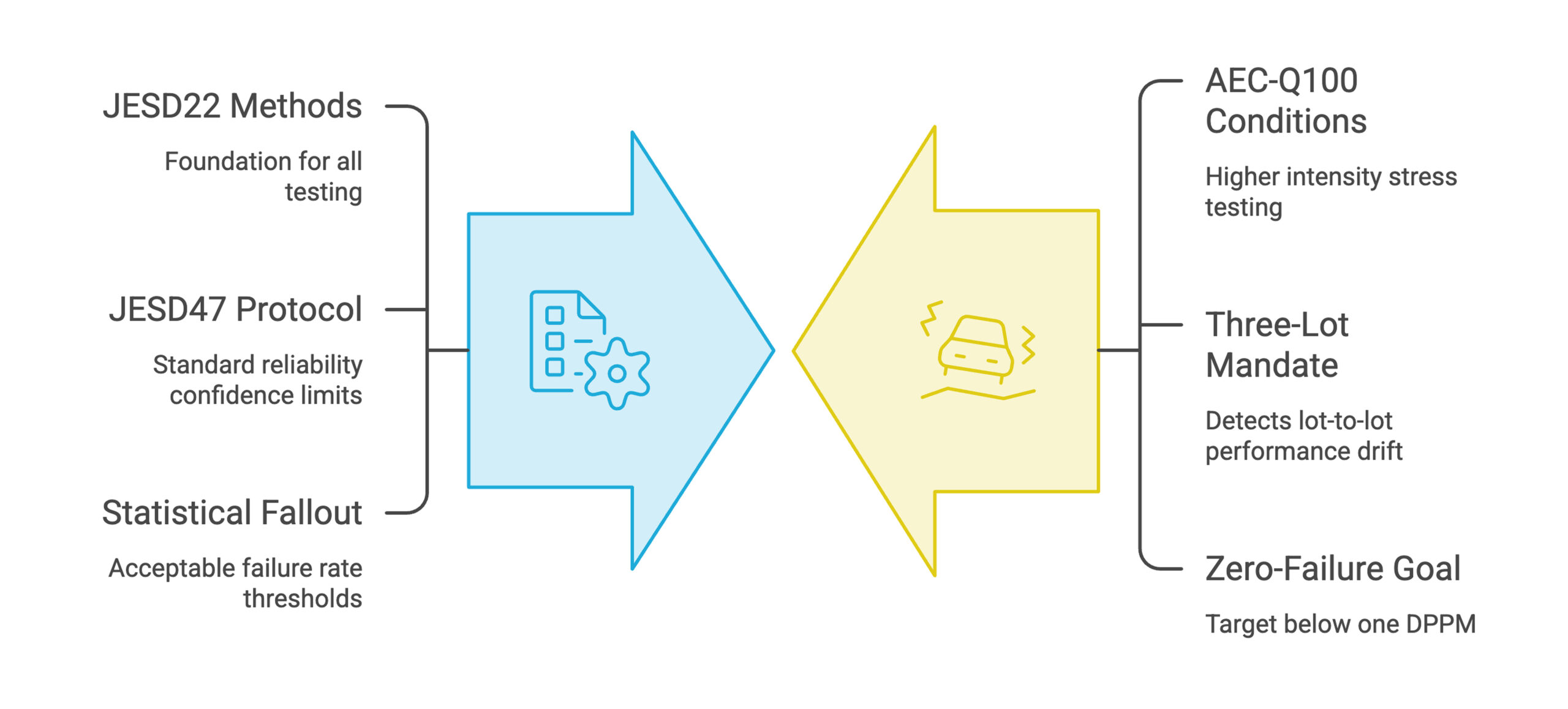
- Same tests, different intensity: HTOL, TC, HAST are all run under JESD22 methods regardless of market. AEC-Q100 simply turns the dial harder (higher Tj, more cycles, larger samples).
- The ‘three lots’ rule is automotive-specific: JESD47 typically accepts one lot. Automotive’s three-lot mandate is what catches lot-to-lot drift before it reaches an OEM line.
- Zero-failure vs. statistical fallout: AEC-Q100 demands zero failures across 231 (or 2400) units. JESD47 accepts statistical fallout within reliability/confidence limits.
- DPPM gap is ~100×: Consumer markets tolerate ~300 DPPM; automotive targets <1 DPPM. This drives every other Q100 difference.
- JESD22 is not a ‘choice’ — it is the underlying method set used by BOTH Q100 and JESD47. If you see a JESD22 reference in either standard, it tells you HOW to run the test, not WHETHER to run it.
- A device qualified to JESD47 is NOT automotive-qualified. You cannot ‘upgrade’ a consumer-grade qualification to automotive without re-running tests at Q100 conditions.
6. Tessolve’s Role in AEC-Q100 Qualification
Managing an end-to-end AEC-Q100 program requires lab infrastructure, ATE platforms, and engineering expertise that most fabless companies lack in-house. Tessolve’s Reliability and Qualification Lab, along with its Test Lab, addresses this gap by conducting environmental stress tests, lifetime simulations, and electrical verification tests (groups A, B, and E).
These services are provided alongside ATE-based test engineering for automotive systems-on-chips (SoCs), power management integrated circuits (PMICs), and sensor integrated circuits (ICs). With over twenty years of experience in semiconductor and automotive engineering, including qualification work on Grade 2 AEC-Q100 automotive wireless programs, Tessolve helps suppliers transition from design to qualified, field-ready silicon more efficiently.
Frequently Asked Questions (FAQs)
1. Is AEC-Q100 a legal regulation?
No. AEC-Q100 is a contractual standard, not a regulation. However, all major OEMs (and Tier-1s acting on their behalf) include it as a Customer-Specific Requirement (CSR) in PPAP submissions, making it de-facto mandatory.
2. What is the current revision of AEC-Q100?
AEC-Q100 Rev-J / J1 is the current public release on aecouncil.com. Most legacy qualification reports still reference Rev-H (Sept 2014) or Rev-I (May 2017). Rev-J introduces BTI testing, updated ESD requirements for 28 nm / RF devices, revised TC conditions, and additional FC-BGA tests.
3. Can I use the same qualification data for Grade 0 if I qualified at Grade 1?
No. Grade 0 requires re-qualification at the higher temperature (e.g., Tj for HTOL bumped up, TC extended to –65 °C/+150 °C, HTSL at higher temperature). Generic data is only allowed if the family member was tested at equal-or-harsher conditions.
4. What is ‘generic data’ and when can it be used?
Generic data is reliability data from a previously qualified part within the same Qualification Family (same wafer fab, same process node, same package family). It can substitute for new testing if the data is less than 5 years old and the part is structurally similar. This is one of the biggest cost-savers in qualification planning.
5. Is HTOL alone enough to claim ‘automotive qualified’?
No. HTOL is just one test in Group B. AEC-Q100 requires all applicable Group A through G tests to pass with zero failures. A claim of ‘AEC-Q100 qualified’ implies the full suite has been executed and documented.
6. How does AEC-Q100 relate to ISO 26262?
They are complementary but distinct. AEC-Q100 covers component-level random hardware failure rates (FIT). ISO 26262 covers functional-safety system-level requirements (ASIL classification, FMEDA, SPFM/LFM metrics). A device can be AEC-Q100 qualified but still not be ‘functional-safety capable’ unless additional ISO 26262 work is done.
7. What is the acceptance criterion for AEC-Q100 stress tests?
Zero failures across all qualification sample units. Any single failure triggers root-cause analysis, corrective action, and full re-qualification. This is the ‘zero-defect’ philosophy that drives automotive DPPM targets.
8. Does AEC-Q100 cover board-level reliability?
No. AEC-Q100 is purely component-level. Board-level drop, bend, BLR (Board-Level Reliability), and reflow tests are handled by JEDEC JESD22-B111, IPC-9701, and OEM-specific tests like Bare Reel Drop Test for WLCSP.
9. How long does a typical AEC-Q100 qualification take?
Critical-path tests (HTOL 1000 h, TC 1000 cycles, HAST 96 h or THB 1000 h) drive the timeline. Plan for 14–18 weeks end-to-end including PC, build, stress, and electrical readouts — assuming all goes well on first pass.
10. Is burn-in mandatory for AEC-Q100?
Burn-in itself is not mandatory if ELFR (B2) demonstrates acceptable infant mortality. If ELFR fallout exceeds target, then burn-in or PAT screening (AEC-Q001/Q002) becomes a required production screen.
11. How does AEC-Q100 handle Cu wire bonded devices?
Special qualification requirements per AEC-Q006 apply (added in Rev-I). Additional HAST/UHST stress and tighter Cpk on wire pull/shear are typically required.
12. What about chiplets and multi-die packages?
Single-die ICs follow AEC-Q100; multi-chip modules (MCMs, 2.5D/3D, chiplets) fall under AEC-Q104, which references back to Q100 for individual die qualification plus additional interposer/TSV/bridge tests.
8. Closing Thoughts
AEC-Q100 is not just a checklist — it is a discipline. Done well, it forces collaboration between design, process, packaging, test, and reliability teams to systematically eliminate failure mechanisms BEFORE the device reaches a customer’s ECU. Done poorly, it becomes a paperwork exercise that produces qualified parts which still fail in the field.
Practical recommendations from the trenches:
- Lock the Qualification Family definition early — it determines what generic data you can leverage and what you must re-test.
- Build the qualification test plan (QTP) at the same time as the test program is being developed — late changes to PC, end-points, or read-points are expensive.
- Treat ELFR as a process-control tool, not a one-time gate; track DPPM trends quarterly.
- For advanced nodes (≤16 nm, 7 nm, 5 nm) plan early for BTI and aging-aware design margin — Rev-J reflects this industry shift.
- Align AEC-Q100 with ISO 26262 FMEDA work upstream; closing the loop later is painful.
Partnering with an experienced qualification lab can significantly improve the PPAP submission process for teams, preventing costly retesting cycles. Tessolve’s combination of reliability labs, ATE test infrastructure, and automotive domain expertise supports exactly this, helping suppliers execute AEC-Q100 test groups accurately the first time.
9. Source Documents & References
Primary AEC Documents (publicly available at www.aecouncil.com):
- AEC-Q100 Rev-J1 – Failure Mechanism Based Stress Test Qualification for Integrated Circuits (Base document)
- AEC-Q100-001 Rev-C – Wire Bond Shear Test
- AEC-Q100-002 Rev-E – Human Body Model (HBM) ESD Test
- AEC-Q100-004 Rev-D – IC Latch-Up Test
- AEC-Q100-005 Rev-D1 – NVM Endurance, Data Retention & Operational Life Test
- AEC-Q100-007 Rev-B – Fault Simulation and Test Grading
- AEC-Q100-008 Rev-A – Early Life Failure Rate (ELFR)
- AEC-Q100-009 Rev-B – Electrical Distribution Assessment
- AEC-Q100-010 Rev-A – Solder Ball Shear Test
- AEC-Q100-011 Rev-D – Charged Device Model (CDM) ESD Test
- AEC-Q100-012 – Short Circuit Reliability of Smart Power Devices (12 V)
- AEC-Q001 – Statistical Yield Analysis (PAT)
- AEC-Q002 – Statistical Bin Limits (SBL)
- AEC-Q003 – Electrical Characterization Guidelines
- AEC-Q005 – Pb-Free Component Requirements
- AEC-Q006 – Copper Wire Bond Qualification Requirements
Referenced JEDEC / Industry Standards:
- JESD22-A101 – Steady-State Temperature Humidity Bias (THB)
- JESD22-A102 – Accelerated Moisture Resistance – Autoclave
- JESD22-A103 – High Temperature Storage Life (HTSL)
- JESD22-A104 – Temperature Cycling
- JESD22-A105 – Power & Temperature Cycling (PTC)
- JESD22-A108 – Temperature, Bias, and Operating Life (HTOL)
- JESD22-A110 – Highly Accelerated Temperature & Humidity Stress (HAST)
- JESD22-A113 – Preconditioning of Non-hermetic SMD
- JESD22-A118 – Unbiased HAST
- JESD22-B100 / B108 – Physical Dimensions
- JESD22-B102 – Solderability
- JESD22-B105 – Lead Integrity
- JESD22-B111 – Board-Level Drop Test
- JESD22-B113 – Board-Level Cyclic Bend
- JESD35 – TDDB Procedure for Gate Dielectrics
- JESD47 – Stress-Test-Driven Qualification of ICs (industrial / consumer baseline)
- JESD60 – Hot Carrier Injection (HCI) Procedure
- JESD61 – Electromigration
- JESD87 – Stress Migration
- JESD89 – Soft Error Rate Measurement
- JEP122 – Failure Mechanisms and Models for Semiconductor Devices (BTI ref.)
- J-STD-020 – Moisture/Reflow Sensitivity Classification (JEDEC/IPC)
- J-STD-002 – Solderability of Component Leads/Terminations
- ANSI/ESDA/JEDEC JS-001 – HBM ESD Test (current industry method)
- ANSI/ESDA/JEDEC JS-002 – CDM ESD Test
- MIL-STD-883 – Test Methods for Microelectronics (referenced for WBP, mechanical, hermetic)
- ISO 26262 – Functional Safety for Road Vehicles
- IATF 16949 – Automotive Quality Management System
- IPC-9701 – Performance Test Methods for Surface-Mount Solder Attachments
- IEC 60068 – Environmental Testing (system-level reference)